


As global urban centers face increasingly severe heatwaves, the energy demands of mechanical air conditioning are straining power grids and worsening microclimate urban heat island effects. Conventional compressor-based HVAC systems rely on massive electricity inputs and chemical refrigerants—such as hydrofluorocarbons (HFCs)—that possess high global warming potential. In response, modern architects, building engineers, and sustainability researchers are revisiting ancient passive thermal principles. Among the most effective, low-carbon innovations emerging today is the terracotta evaporative cooling system.
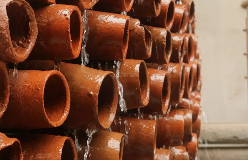

By combining the micro-porous properties of low-fired earthenware with fundamental thermodynamic principles, a terracotta evaporative cooling system offers a zero-refrigerant, ultra-low-energy cooling solution for both interior and semi-open architectural environments. Rooted in traditional vernacular objects like the Indian matka (clay water pot) and kulhad (un-glazed terracotta cup), this approach converts accessible, eco-friendly materials into scalable passive thermal equipment.
This comprehensive technical analysis explores the physics, material dynamics, practical construction, and architectural deployment of the terracotta evaporative cooling system. Whether you are designing a compact residential courtyard, retrofitting an uninsulated classroom, or engineering a double-skin building envelope, this guide outlines the parameters required for maximum thermal efficiency when specifying a terracotta evaporative cooling system.
1. The Physics and Material Thermodynamics of the Terracotta Evaporative Cooling System
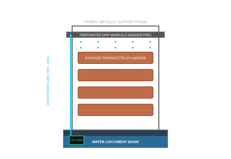
Understanding why a terracotta evaporative cooling system performs so effectively requires examining the latent heat transfers and capillary dynamics within porous ceramics.
       [ Warm, Dry Outdoor Air ] ===> ( Air Stream Enters Conduit )
                                               |
                                               v
   +-------------------------------------------------------------------+
   |  Terracotta Wall saturated via Micro-Capillary Transport           |
   |                                                                   |
   |  * Sensible Heat from air transfers to surface water film         |
   |  * Liquid Water shifts to Vapor (Latent Heat of Vaporization)      |
   +-------------------------------------------------------------------+
                                               |
                                               v
       [ Cooled, Moderately Humid Air Flow ] ===> ( Temperature drops 6°C - 10°C )
Sensible Heat Conversion to Latent Heat
Evaporative cooling occurs when liquid water transforms into vapor by absorbing heat energy from its surrounding environment. Thermal physics divides heat into two primary operational states:
- Sensible Heat: The kinetic heat energy measurable via a standard dry-bulb thermometer.
- Latent Heat: The energy absorbed or released during a phase change (such as liquid water converting to vapor) without changing the material’s temperature.
When ambient air passes over a moist terracotta surface, sensible heat from the air stream is transferred to the film of water clinging to the clay. The water molecules absorb this energy, overcome their intermolecular bonds, and evaporate into the air stream as moisture vapor. This phase change extracts sensible heat from the air, causing a rapid drop in dry-bulb air temperature while slightly increasing relative humidity.
The heat absorption process during water evaporation within a terracotta evaporative cooling system is expressed by the fundamental thermodynamic equation recorded by the NIST Standard Reference Data:
$$Q = m \cdot L_v$$
Where:
- $Q$ is the total thermal energy removed from the air stream (in Joules).
- $m$ is the mass of water evaporated (in kilograms).
- $L_v$ is the latent heat of vaporization of water (approximately $2.26 \times 10^6 \text{ J/kg}$ at $25^\circ\text{C}$).
Because water has an exceptionally high latent heat of vaporization, even modest rates of water evaporation yield substantial cooling effects on passing air currents.

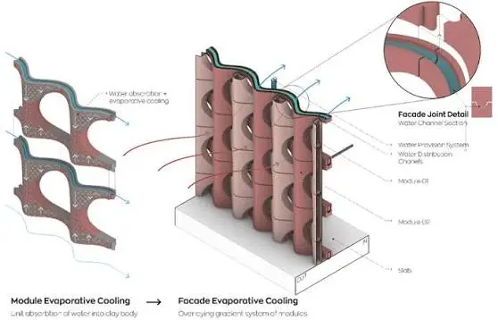
Capillary Water Transport in Unglazed Terracotta
Unglazed terracotta is fired at relatively low temperatures ($900^\circ\text{C}$ to $1050^\circ\text{C}$). This preserves an interconnected capillary network throughout the clay body. When water contacts the interior wall or reservoir of a terracotta evaporative cooling system, capillary pressure draws the liquid outward toward the exterior surface.
The height and rate of capillary liquid transport within porous ceramic media are governed by Jurin’s Law:
$$h = \frac{2\gamma \cos\theta}{\rho g r}$$
Where:
- $h$ is the capillary draw height (meters).
- $\gamma$ is the surface tension of water ($\text{N/m}$).
- $\theta$ is the contact angle between liquid water and the terracotta pore wall.
- $\rho$ is liquid water density ($\text{kg/m}^3$).
- $g$ is gravitational acceleration ($9.81 \text{ m/s}^2$).
- $r$ is the mean pore radius of the fired clay matrix (meters).
This continuous capillary action ensures the outer surfaces of a terracotta evaporative cooling system remain evenly moist without requiring high-pressure misters or atomizing nozzles. As warm ambient winds sweep through the clay conduits, evaporation occurs steadily along the damp ceramic boundary layer. The thermal performance and efficiency of a terracotta evaporative cooling system depends directly on keeping these microscopic pores free of mineral blockages.
2. Case Study: Project Vaayu as a Terracotta Evaporative Cooling System
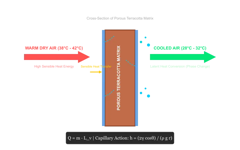
A clear real-world demonstration of the terracotta evaporative cooling system in action is Project Vaayu, an eco-cooling initiative created by student innovators at The Shri Ram School, Moulsari.
+-----------------------------------------------------------------------+
|                       PROJECT VAAYU SCHEMATIC                         |
+-----------------------------------------------------------------------+
|                                                                       |
|      [ Top Water Distribution Header Pipe / Drip Manifold ]           |
|      =======================================================          |
|         ||               ||               ||               ||         |
|         \/               \/               \/               \/         |
|     ( Terracotta )   ( Terracotta )   ( Terracotta )   ( Terracotta ) |
|     ( Cup Array  )   ( Cup Array  )   ( Cup Array  )   ( Cup Array  ) |
|     (  "Kulhad"  )   (  "Kulhad"  )   (  "Kulhad"  )   (  "Kulhad"  ) |
|         ||               ||               ||               ||         |
|         \/               \/               \/               \/         |
|     +-----------------------------------------------------------+     |
|     |            Lower Catchment Basin & Sump Tank             |     |
|     +-----------------------------------------------------------+     |
|                                  ^                                    |
|                                  | (12V DC Low-Wattage Pump)          |
|                                  +------------------------------------+
+-----------------------------------------------------------------------+
The Thermal Challenge in Public Classrooms
During extreme dry heat seasons in South Asia, indoor classroom temperatures in uninsulated public school buildings often exceed 40°C. Standard electric air conditioners are financially unviable for many underfunded schools due to high equipment costs, unreliable electrical infrastructure, and high monthly utility bills. High indoor heat leads to physical fatigue, reduced cognitive performance, and lower attendance among students.
The Low-Tech Architectural Solution
To address this challenge, student researchers developed Project Vaayu—an open-source terracotta evaporative cooling system that utilizes upcycled earthenware cups (kulhads), recycled structural framing, and a low-wattage water circulation pump.
“When we explain it, people immediately connect it to matkas, the clay pots that keep water cool. That’s when they ask, ‘Why isn’t this everywhere already?'”
— Project Vaayu Student Team
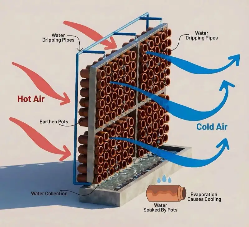
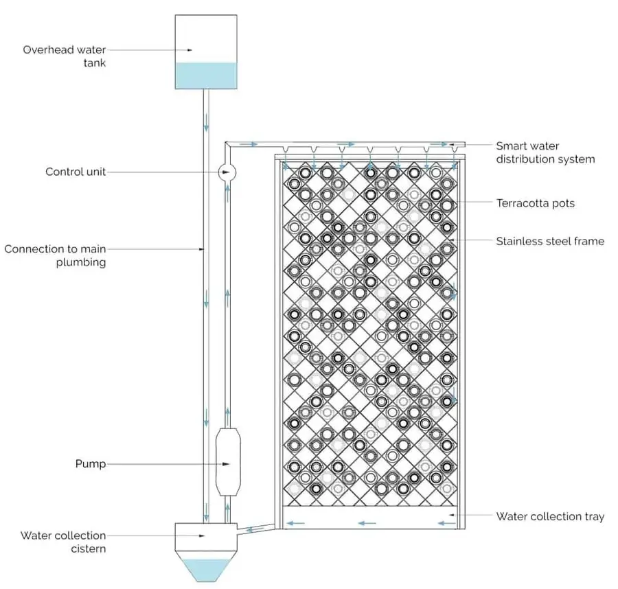
The unit features a vertical frame filled with dozens of hollow cylindrical kulhads stacked horizontally. A small submerged pump draws water from a bottom catch basin to a perforated top manifold. Water trickles down over the interconnected ceramic exterior walls, saturating the porous clay matrix. Warm air passing through the cylindrical openings drops in temperature before entering the classroom, making this terracotta evaporative cooling system both affordable and practical.
Primary Engineering Advantages
Building a localized terracotta evaporative cooling system provides significant engineering benefits over conventional solutions:
- Upcycled Circular Materials: Uses low-cost, readily available clay cups (kulhads) and scrap timber, keeping initial material costs low while diverting waste.
- Minimal Power Demand: Operates on a single 10W–25W DC water pump, which can be powered by a single small solar panel or backup battery.
- Zero Synthetic Refrigerants: Completely avoids harmful fluorinated gases (like R-22, R-410A, or R-32), eliminating direct GWP emissions.
- Demonstrated Temperature Drops: Field testing confirms local dry-bulb air temperature reductions of 6°C to 10°C under warm, low-humidity operating conditions.
3. Step-by-Step Blueprint to Build a Terracotta Evaporative Cooling System
For architects, facility managers, and eco-builders seeking to build a prototype terracotta evaporative cooling system, this construction blueprint details the required component specifications and assembly sequence.
+--------------------------------------------------------------------+
|                FABRICATION & ASSEMBLY TIMELINE                     |
+--------------------------------------------------------------------+
| Phase 1: Structural Frame Assembly & Basin Waterproofing           |
| --> Construct timber/steel frame; seal catchment basin lining.     |
+--------------------------------------------------------------------+
| Phase 2: Clay Component Preparation & Micro-Pore Saturation        |
| --> Clean terracotta cups; drill airflow ports; submerge 24 hours. |
+--------------------------------------------------------------------+
| Phase 3: Stacking Matrix & Modular Securing                        |
| --> Stack cups horizontally; fasten with stainless wire grid.       |
+--------------------------------------------------------------------+
| Phase 4: Plumbing Circuit & Recirculation Integration              |
| --> Mount pump, connect riser tube, position drip manifold header.|
+--------------------------------------------------------------------+
| Phase 5: Hydronic Balancing & Flow Calibration                     |
| --> Balance drip rates across top row; optimize capillary wetness. |
+--------------------------------------------------------------------+
Required Components and Specifications
- Clay Modules: 120 to 250 unglazed terracotta cups (kulhads) or extruded cylindrical clay tiles ($70\text{mm} – 100\text{mm}$ diameter, $120\text{mm} – 150\text{mm}$ length).
- Structural Frame: Weather-resistant teak, bamboo, or powder-coated 20mm steel angle profiles.
- Hydronic Subsystem:
- 1x Submersible 12V DC water pump (Flow rate: 300 to 500 liters/hour; Power: 12W – 18W).
- 12mm silicone delivery hose and 1/2-inch perforated PVC distribution header.
- Corrosion-resistant stainless steel or plastic catchment reservoir tray.
- Fasteners & Filtration: 316 stainless steel binding wire, mesh sediment screen, and outdoor silicone sealant.
Step 1: Structural Frame and Reservoir Setup
Assemble a rigid rectangular frame designed for the intended wall opening or freestanding location. Mount the catchment basin at the base, ensuring all internal seams are sealed with waterproof silicone or liquid rubber membrane. The reservoir must hold enough water to cover the pump intake completely during operation.
Step 2: Preparing the Terracotta Media
Examine each terracotta unit for structural fractures. If using closed-bottom kulhads, carefully cut or drill a central aperture ($25\text{mm} – 40\text{mm}$ diameter) through the base of each cup to allow unobstructed airflow through the cylinder. Submerge all clay units in clean water for 24 hours prior to installation to saturate the ceramic pore network completely.
Step 3: Assembling the Clay Matrix
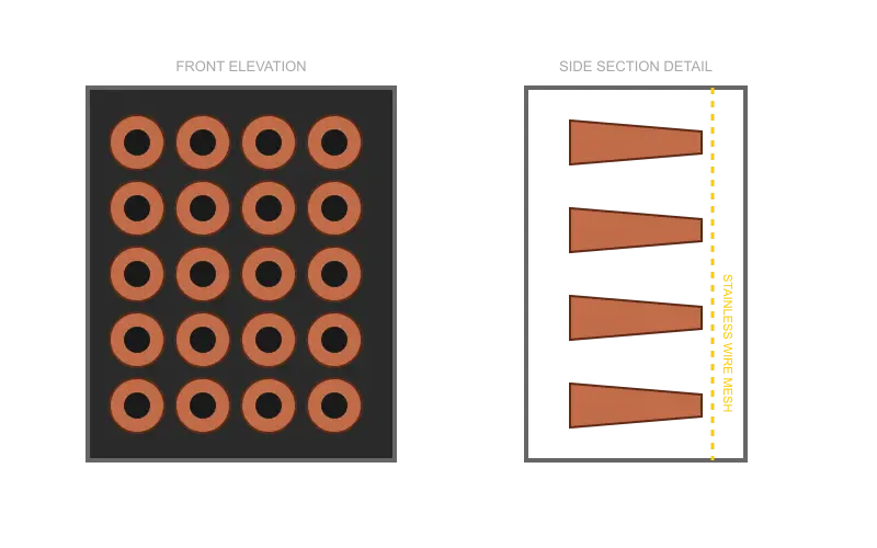
When constructing the matrix of a terracotta evaporative cooling system, stack the terracotta cylinders horizontally in an overlapping honeycomb or grid array within the frame. Orient the open apertures parallel to the prevailing airflow. Fasten each row using stainless steel tie wire connected to a rear wire mesh grid. Leave small uniform inter-element gaps so trickling water can flow down over every layer.
Step 4: Installing the Hydronic System
Position the submersible pump in the lower catchment basin. Connect the pump output to a vertical delivery hose running up to the top distribution header pipe. Drill 2mm drip holes spaced every 30mm along the underside of the header pipe to distribute water evenly across the top row of terracotta components. Place a stainless steel mesh strainer above the pump intake to filter out airborne dust and clay particles.
Step 5: System Calibration and Testing
Fill the catchment basin with clean water and turn on the pump. Adjust the main control valve until water drips evenly across the top row of clay units and flows down through the entire matrix without splashing outside the tray. Place the completed terracotta evaporative cooling system within an open window frame, courtyard doorway, or wind path to begin passive cooling.
4. Architectural Integration of the Terracotta Evaporative Cooling System
A terracotta evaporative cooling system can extend beyond small desktop models or localized units. Modern sustainable practices scale these modular ceramic assemblies into functional architectural facades, interior partitions, and microclimate regulators.
+-----------------------------------------------------------------------+
|                  ARCHITECTURAL PLACEMENT ZONES                        |
+--------------------------+--------------------------------------------+
| Semi-Open Courtyards     | Pre-cools cross-breezes entering interiors |
+--------------------------+--------------------------------------------+
| Double-Skin Facades      | Intercepts and reduces solar radiant heat  |
+--------------------------+--------------------------------------------+
| Terraces & Verandas      | Buffers heat gains on exposed outdoor decks|
+--------------------------+--------------------------------------------+
| Passive Wind Towers      | Cools down-draft airflow in vertical shafts|
+--------------------------+--------------------------------------------+
To explore further architectural integration frameworks, passive design strategies, and HVAC reduction methods, review our comprehensive passive cooling design guide.
Semi-Open Courtyards and Lightwells
In warm, arid climates, central courtyards act as primary thermal sinks for residential and commercial buildings. Installing a vertical terracotta evaporative cooling system along the windward side of a courtyard allows incoming breezes to be pre-cooled before entering surrounding rooms. This configuration creates a microclimate zone that lowers courtyard ground temperatures and improves natural ventilation across adjoining corridors. Detailed design patterns for integrating native ceramics in building envelopes are available in our sustainable materials guide for terracotta.
[ Outdoor Wind ] ---> [ Terracotta Cooling Screen ] ---> [ Cooled Courtyard ] ---> [ Living Spaces ]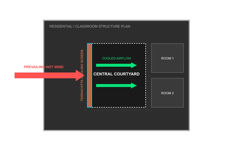
Double-Skin Ventilated Building Facades
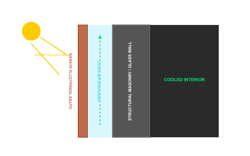
Architects can integrate custom extruded terracotta modules into double-skin facade assemblies. Mounted as an exterior breathable skin, a terracotta evaporative cooling system intercepts direct solar radiation before it hits the inner structural wall. Water supplied via a solar-powered top distribution line moistens the inner surface of the clay screen, cooling the air cavity between the glass/masonry wall and the outer facade. This design reduces solar heat gains and lowers air conditioning loads for the building envelope.
       Sunlight
          ||
          \/
+-------------------+      Air Cavity       +-------------------+
|  Outer Terracotta | <--- [ Evaporative ]  |  Inner Structural |
|  Screen (Moist)   |      [ Cooling     ]  |  Glass/Brick Wall |
+-------------------+      [ Zone        ]  +-------------------+
For technical calculations on microclimate airflow optimization and courtyard orientation, consult our courtyard thermal dynamics study.
Terraces, Verandas, and Urban Patios
Rooftop decks and verandas often suffer from elevated radiant temperatures during midday hours. A freestanding terracotta evaporative cooling system screen placed along the perimeter of a terrace acts as a wind filter and thermal buffer. It provides localized cooling for outdoor seating areas without requiring high-pressure misters that cause surface wetness or maintenance issues.
Passive Wind Towers and Down-Draft Shafts
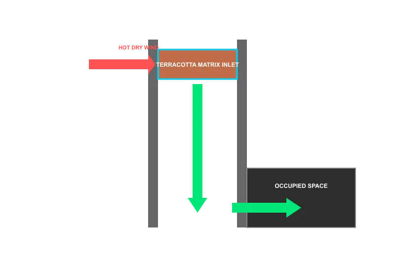
By integrating a terracotta evaporative cooling system into the upper inlet of a vertical wind tower (or badgir), designers can create passive down-draft evaporative cooling systems (PDEC). As hot dry air enters the top of the tower, it passes through wet ceramic conduits, grows denser as it cools, and naturally descends down the shaft into occupied lower spaces without mechanical fans.
5. Performance Benchmarking for the Terracotta Evaporative Cooling System
To evaluate the operational and environmental advantages of integrating a terracotta evaporative cooling system, the following comparison matrix details key operational metrics against conventional HVAC equipment evaluated according to ASHRAE Equipment Standards:
| Operational Parameter | Terracotta Evaporative Cooling System | Conventional Split Air Conditioner | Commercial Industrial Desert Cooler |
| Primary Cooling Mechanism | Capillary Evaporative Heat Exchange | Vapor Compression Cycle (Compressor) | Forced-Air Wet Synthetic Pad Evaporation |
| Refrigerant Medium | Pure Water (Zero Chemical Coolants) | Synthetic HFCs / HCFCs (e.g., R-410A, R-32) | Pure Water |
| Hourly Power Consumption | 10W – 30W (Pump power only) | 1200W – 2200W per 1.5-ton unit | 180W – 350W (Fan and pump) |
| Embodied Carbon Profile | Low (Abundant low-fired local clay) | High (Mined metals, electronics, synthetic polymers) | Moderate (Injection-molded plastics, metals) |
| Average Temperature Reduction | 6°C to 10°C (Hot, dry ambient conditions) | 10°C to 16°C (Set-point controlled) | 4°C to 8°C |
| Architectural Integration Value | High (Custom ceramic screens, bio-textures, facades) | Low (Monolithic interior/exterior utility boxes) | Low (Bulky mobile equipment units) |
| Operational Sound Level | Very Low ($< 30 \text{ dBA}$ trickle sound) | Moderate ($42 – 55 \text{ dBA}$ compressor fan) | High ($60 – 72 \text{ dBA}$ high-rpm fan noise) |
| Recommended Spatial Context | Semi-open courtyards, ventilated rooms, verandas | Hermetically sealed indoor rooms | Large open hall spaces |
Lifecycle Carbon and Refrigerant Analysis
The environmental performance of modern building cooling equipment extends beyond operational energy use. To calculate structural cooling loads, utilize our building envelope energy performance calculator.
       CONVENTIONAL AIR CONDITIONER           TERRACOTTA EVAPORATIVE SYSTEM
   +---------------------------------+     +---------------------------------+
   | Metal Mining & Processing       |     | Natural Local Clay Extraction   |
   | Synthetic Chemical Refrigerants |     | Low-Temperature Firing / Upcycle|
   | 1500W Operational Draw          |     | 15W Operational Draw            |
   | High E-Waste at End-of-Life     |     | 100% Biodegradable Clay Media   |
   +---------------------------------+     +---------------------------------+
Embodied Carbon
Standard air conditioning units require energy-intensive metals (copper, aluminum, steel), rare Earth electronics, and synthetic insulation materials. By contrast, a terracotta evaporative cooling system relies primarily on abundant local clay fired at low temperatures or upcycled ceramic waste (such as discarded kulhads). At the end of its operational lifecycle, the terracotta media is non-toxic, chemically inert, and fully biodegradable or crushable for reuse in brick manufacturing.
Operational Energy Reduction
A standard 1.5-ton residential split air conditioner consumes approximately $1.5 \text{ kWh}$ of electrical energy per hour of operation. In contrast, a terracotta evaporative cooling system requires only $0.015 \text{ kWh}$ to power its small recirculating water pump. This represents up to a 98% reduction in operational electricity demand. Operating a terracotta evaporative cooling system continuously delivers noticeable temperature drops without causing high power bills. When connected to a small 30W off-grid photovoltaic panel, the entire terracotta evaporative cooling system operates with zero operational carbon emissions.
6. Maintenance Protocols for Your Terracotta Evaporative Cooling System
To maintain optimal thermal performance, a terracotta evaporative cooling system requires simple, routine maintenance. For detailed facility guidelines, check our architectural maintenance and longevity standards.
+-------------------------------------------------------------------------+
|                  PREVENTATIVE MAINTENANCE SCHEDULE                      |
+------------------+------------------------------------------------------+
| Weekly Task      | Flush catchment tray; clean pump intake mesh screen. |
+------------------+------------------------------------------------------+
| Monthly Task     | Inspect clay array for mineral scaling or dust cover.|
+------------------+------------------------------------------------------+
| Seasonal Task    | Run mild vinegar flush cycle to clear micro-pores;   |
|                  | allow full dry-out cycle to prevent mold growth.     |
+------------------+------------------------------------------------------+
Managing Mineral Scaling (Efflorescence & Hard Water Deposits)
In regions where supply water has high mineral content (calcium and magnesium ions), mineral salts can deposit on exterior terracotta surfaces as water evaporates. To properly care for a terracotta evaporative cooling system, routine flushing of mineral deposits is recommended so heavy scaling does not clog the micro-capillaries of the clay.
Operational Tip: To remove scale buildup without damaging the terracotta matrix, run a mild acidic flush cycle through the system. Add food-grade white vinegar to the water basin in a $1:10$ ratio with clean water and run the pump for two hours during non-occupancy periods. The mild acid dissolves calcium carbonate scale, clearing the pore network. Rinse the basin thoroughly with fresh water before resuming normal operation of your terracotta evaporative cooling system.
Biological Control and Algae Prevention
Operating a terracotta evaporative cooling system with clean water prevents algae or bio-film formation on the moist ceramic matrix. Implement these preventative steps:
- Periodic Dry Cycles: Turn off the water pump for 4 to 6 hours once a week while allowing natural air movement to pass through the frame. Drying out the terracotta media naturally stops algae growth.
- Natural Copper Biocide: Place a small piece of clean copper tubing or a copper plate inside the lower water catchment basin of the terracotta evaporative cooling system. Copper ions dissolved in micro-quantities act as a safe, natural algaecide, keeping the recirculating water clean.
7. FAQs About the Terracotta Evaporative Cooling System
What is a terracotta evaporative cooling system?
A terracotta evaporative cooling system is a passive thermal management installation built from porous fired clay components, water distribution tubing, and a structural frame. It cools air by drawing water through ceramic capillaries to its exterior surface; as warm air passes over the wet clay, water evaporates, absorbing sensible heat and lowering the air temperature naturally.
How much temperature drop can a terracotta evaporative cooling system achieve?
In dry or semi-arid climates with low relative humidity, a terracotta evaporative cooling system can reduce dry-bulb air temperatures by 6°C to 10°C. Performance depends on ambient wet-bulb depression: drier incoming air yields greater water evaporation and higher cooling performance within the terracotta evaporative cooling system.
Does a terracotta evaporative cooling system work in high-humidity climates?
Evaporative cooling principles depend on ambient relative humidity. In humid coastal environments ($>75\% \text{ RH}$), the rate of water evaporation in a terracotta evaporative cooling system is lower, resulting in smaller dry-bulb temperature drops ($2^\circ\text{C} – 4^\circ\text{C}$). However, the system still functions effectively as an exterior thermal buffer, solar heat shield, and air pre-cooler for semi-open architectural spaces.
How much electricity does a terracotta evaporative cooling system use?
A standard residential or classroom-scaled terracotta evaporative cooling system uses between 10 Watts and 30 Watts of electric power—only what is required to run a low-voltage water pump. This yields up to a 98% reduction in energy use compared to standard mechanical air conditioners.
What inspired Project Vaayu’s eco-cooler design?
Project Vaayu was developed by student researchers at The Shri Ram School to address extreme classroom heat in underfunded schools. Inspired by the traditional Indian matka (clay pot) and kulhad (terracotta cup), the team created a modular terracotta evaporative cooling system using stacked clay cups, recycled framing, and low-power pumps to deliver affordable cooling.
8. The Future of the Terracotta Evaporative Cooling System in Sustainable Design
As energy costs rise and urban environments face higher summer temperatures, relying exclusively on mechanical air conditioning is increasingly unsustainable. The terracotta evaporative cooling system shows how traditional material wisdom can combine with modern building science to provide high-performance thermal comfort.
By adopting modular ceramic cooling screens, architects, facility directors, and eco-innovators can lower building energy consumption, eliminate synthetic refrigerants, and create resilient, heat-adapted indoor and semi-open environments. Inspired by initiatives like Project Vaayu, integrating a terracotta evaporative cooling system into modern building designs offers an effective path toward sustainable architectural design. Feel free to explore our portfolio of sustainable passive projects to see real-world implementations.
For more Architectural projects, please visit Architecture Associate